Previous: SRN4 Features 
 Next: SRN4 Systems
On this page I will attempt to run through the eight main systems in an SRN4 cockpit, those being: Fuel, Electronics, Flight Controls and Surfaces, Navigation, Propeller Pitch, Engines, Hydraulics and Drive Gearboxes. The reason for this is to give an overview of the controls behind a hovercraft. If you're here on the tour and wondering why this page comes where it does, I have surmised that you've learnt about the various functions and features of hovercraft such as the SRN4, and are now ready to find out how they all fit together in terms of how they are controlled and managed.
The cockpit of an SRN4 is located above the bows of the craft, at the level of the roof. It is accessible via either of two ladders, one running up the outside of the port bow of the craft, and the other inside the car deck leading to a hatch in the ceiling. Three crew man the flight deck, the Captain, the First Officer (Navigator) and the Second Officer (Flight engineer). The Captain has ultimate responsibility for the running, management and steering of the craft however the second officer would often take over various roles.
Overview | Fuel and Electronics | Flight Control Surfaces, Control Inputs, and Propeller Pitch | Throttles and Pitch Selectors| Navigation | Engines | Hydraulics | Drive Gearboxes
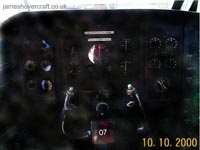
Cockpit of the SRN4
This diagram shows the banks of systems and arrangement of gauges in the cockpit of the SRN4. Although looking quite complex, the cockpit systems are arranged in a logical, clear order, separated into systems for quick-access. It is never the case that the flight crew will look at all the gauges simultaneously. They will instead scan the instrument panels diagonally, looking for anomalies.
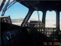
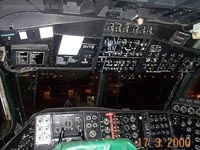
Actual Cockpit
Real-life cockpit showing all of the systems mentioned on this page.
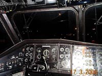
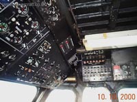
Fuel and Electronics Panel [top]
This photo shows the fuel and electronics overhead panels.
Similar to many aeroplanes, the SRN4 used fuel as more than just the juice to power its engines. Being a hovercraft, stability was key to an efficient ride. Therefore, fuel was also used as ballast, and could be moved around the craft by means of crossfeed valves and pumps, and transfer tanks. The SRN4 therefore had multiple fuel tanks, for this purpose, for fuel storage and for engine supply. Shown in the photograph are a few gauges for fuel quantity (bottom left), and the fuel crossfeed system (top left).
In the middle and of the photo is the electronics panel. The SRN4 generated its electricity by means of two APUs and generators running from its four engines. The power was 3-phase AC (Alternating Current), and low voltage DC (Direct Current), each feeding its own electronic "bus bar". Various craft systems operated from each of these two bus bars, such as the lighting, heating, winches and computers for navigation. Gauges on the electronics panel indicate such factors as voltage, current and condition of the generators. Switches on the panel could be used to select between generators, systems and isolate parts of the system in case of failure.
Flight Control Surfaces, Control Inputs, and Propeller Pitch [top]
To the left and right of the navigation panel are the flight control position indicators and propeller pitch position indicators. These show the captain the positions of each of the pylons and rudders, and the pitch (positive, zero or negative) of each of the propellers. With these indicators the captain can tell if there are any malfunctions in the steering or propulsion systems without having to turn around and look out of the rear cockpit windows.
The captain controls these surfaces and propellers by a mixture of control inputs, namely the 2-axis flight yoke (control column) - rotation axis to swivel the pylons for left/right steering, and a push forward/pull back longitudinal axis to control the amount of propeller pitch.
Propeller pitch can be in three states: Positive, Zero or Negative. Zero pitch is the state at which the propellers are simply windmilling, they provide no thrust. This is used for static hovering at port or at sea. Positive and Negative pitch are the states which the propellers provide either rearward thrust (for forward acceleration) or reverse thrust (for rearward acceleration). The longitudinal position of the flight yoke determines the amount of this pitch applied to the propellers, pulling the column fully back reduces the pitch, pushing fully in increases the pitch to full. When the column is fully out, what the craft loses in thrust energy it gains in lift energy, and the hoverheight increases as a result. The converse is true when the column is pushed fully forward, thus a balance of speed, acceleration and hoverheight can be adjusted with one control.
Finally there are two rudder pedals, used to control the angle of the two rudders and thus the yaw of the craft. Pushing the left pedal rotates the rudders clockwise, yawing the bow to the left, and the opposite occurs when the right pedal is pushed.
A balance of all three controls is required for straight line flight or manoeuvring.
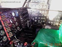
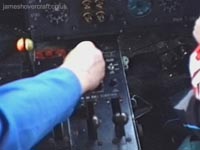
Throttles and Pitch Selectors [top]
The centre console of the cockpit, between the chairs of the two pilots, contains the levers for the engine throttles and propeller pitch mode selectors.
The throttles, the four levers to the right, control in order the fuel flow to engines 1, 2, 3 and 4. Closed Throttle is when the levers are pulled back as far as they can go, stemming the fuel supply to the engines. Full throttle means the levers are fully forward, allowing the most fuel possible to the engines and providing full power.
The other four levers and a few switches on the console control the pitch direction and modes of the four propellers. Each propeller can be individually controlled, to be in positive, zero or negative pitch. As stated above, the control column is then used to determine the amount of pitching required. Cleverly, in the case of a pylon whose propeller is in negative pitch, steering control inputs are automatically reversed, so as to provide better yaw control of the craft.
Also possible from this console is the mode of the pylons. The captain can choose to have all four moving simultaneously, or to have the front two fixed and the rear two as directional controls. This is especially useful for cruise, avoiding as much side slip as possible but still retaining a good degree of steering.
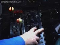
Navigation panel [top]
Navigation across the channel was performed by means of a radio compass, similar to an aircraft's ADF (aerial direction finder), and the radar screens of the Navigator sitting back and to the right of the two front crew in a darkened portion of the flight deck to aid his vision of various navigation computers and RADAR screens.
The photo shows the captain's navigation instruments, notably the compass and tracking indicators. These systems helped achieve a rudimentary heading, and kept the craft on track even during low visibility or high side-slip conditions caused by crosswinds. The top left instrument is an airspeed indicator, deriving its reading from a pitot head protruding from the cockpit roof.
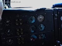
Engines [top]
The engine instruments (bottom right three panels of the cockpit diagram above) are arranged vertically in order of the engine, i.e., from top to bottom, engines 1, 2, 3 and 4. Engines 1 and 2 drive the forward port and starboard propellers/lift fans, and are situated inboard of engines 3 and 4, driving the aft port and starboard propellers/lift fans.
From left to right of the first engine panel in the photo shown here are gauges for compressor RPM, exhaust gas temperature and turbine RPM. The Proteus engine has two shafts and the two RPM readings show the respective speeds of each of these. Exhaust gas temperature (EGT) does exactly what it says.
The four push buttons for each engine are the engine shutdown and emergency shutdown/fire extinguishers. These would be used if an engine displayed signs of malfunction, or there was a malfunction down the line in the drive system, for example an overheating gearbox or a thrown propeller blade.
In-flight speeds of the SRN4's Rolls Royce Marine Proteus gas turbines was in the region of 11,000 RPM.
Hydraulics Panel [top]
This panel in the far corner of the main instrument panel shows various details regarding the craft's hydraulic systems, again in the order of engines 1, 2, 3 and 4. The properties of each system include hydraulic temperatures and pressures, and the status of the pumps and actuators on the craft. Isolation switches and backup reversions were likely to have been present, as redundancy is built into the craft's systems.
Gearboxes [top]
The last set of instruments in the SRN4's cockpit are the gauges measuring various properties of the craft's four main gearboxes, including shaft RPMs, temperatures, oil levels, and output RPMs. The gearboxes split the power between the main propellers and the lift fans, stepping down the RPM from the engine (~ 11,000 RPM) to a more useable value for the thrust and lift systems. Exact values are not known as yet by me!
This concludes the cockpit tour. This page has been put together by pulling together various facts about the craft and similar craft including aeroplanes of the time. Any corrections will be added as and when they are known. If you know a fact to be incorrect please say, and I will correct it ASAP.